Tuning Range
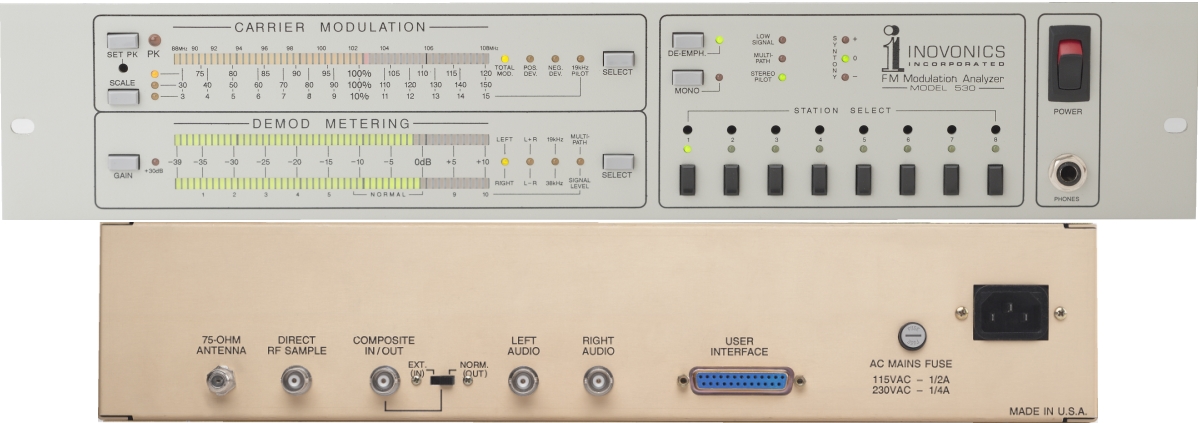
-87-108MHz continuous coverage with 8 station presets.
Receiver Sensitivity
- -2511V (40dBf) for 20dB mono quieting
- -250~1V (60dBf) required for valid Total Modulation Reading
- “F” connector for 75-ohm antenna
- “BNC” connector for alternate 50-ohm RF sample; 10 volts r.m.s.. max.
Carrier Modulation Display
- Quasi-peak response with peak-hold display.
- User-selectable integrations of O.lms. 0.2ms. 0.5ms. 1ms.
- Bargraph display monitors + peaks.- peaks. +-peaks and 19kHz Stereo Pilot.
- Scaling is selectable at 7 5% to 120% in 1% Increments.
- 30%to 150% in 2.5% Increments. and 3% to 15% in 0.25% Increments.
- 100% modulation corresponds to +-75kHz carrier deviation.
- Total Modulation measurement accuracy IS 51%. -tl metering division.
Peak Flasher
- Adjustable between 90% and 120%
- Remote flasher output
Rear-panel BNC connector and IN/OUT switch permit external monitoring of baseband signal from off-air source, or provide input to stereo demod and metering for external baseband feed. Approx. 2 volts p-p corresponds to 100% modulation. 75-ohm output Impedance; lOk-ohm input characteristic.
Baseband Response
Amplitude response of demodulated Composite signal: +0, -0.5dB. 10Hz-60kHz; less than 1.5dB down at 100kHz.
Demod Metering
Dual displays show Left, Right, Stereo Sum, Stereo Difference. 19kHz Pilot, 38kHz Residual, Multipath Distortion and RF Signal Level. Quasi-peak response on +lOdB to -39dB scale, averaging response with additional 30dB gain on -2OdB to -69dB scale. ldB/step metering resolution.
- Program Audio Response: i0.5dB. 20Hz-15kHz
- Noise: Unmodulated (stereo) carrier noise better than 70dB below 100% modulation with de-emphasis.
- Stereo Separation (Composite Input): better than
- 50dB. 50Hz-15kHz
- Stereo Separation (Off-Air): better than 40dB, 50Hz-10kHz; 35dB or better at 15kHz.
- Crosstalk Measurement: M/S and S/M crosstalkmeasurement by stereo sum/difference method andlimited by stereo decoder circuitry. 50dB measurementresolution. 20Hz-5kHz.
Program Signal De-Emphasis
- Switchable IN/OUT from front panel.
- May be jumpered for 75us or 50us.
Audio Outputs
- Front-panel headphone jack monitors program audio.
- OdBu unbalanced outputs at rear-panel BNC test connectors.
- OdBm, 600-ohm balanced program line outputs at rear-panel USER INTERFACE connector.
User Interface
Measurements, Indicators and alarms are brought-out to a rear-panel DB-25 connector so that any monitoring function may be duplicated at a remote location.
Power Requirements
-105-130VAC and 210-260VAC, 50/60Hz; 15W.
Size and Weight
-3.5”H x 19”W x 12”D (2U): 11 Ibs.


